Network Topology:
"Router on a stick" is a network
configuration where a single router is connected to a switch via one physical
interface but can manage multiple VLANs (Virtual Local Area Networks). In this
scenario we used VLAN10 and VLAN20 for different groups for different
purpose.
This setup allows the router to route traffic between VLANs on the switch, acting as a gateway for inter-VLAN communication.
Objectives
- Build the network and configuration basic Cisco Router
- Configuration Gateway for all vlan at Router
- Creating VLANs
- Configuration Trunking / Access at Switch Layer 2
Step 1: In first setup, Cisco Router question to you about initial configuration dialog. You should be type “no” bypass this step
Step 2: You must be basic configuration for Router as following
|
Commands |
|
|
|
User mode |
|
|
Moving to Privilege mode |
|
|
Moving to global config |
|
|
Config hostname from
Router to R1 |
|
R1 (config)# banner motd
#This is Router # |
Config banner message |
|
|
Set password login from
user mode to Privilege |
|
|
Request Router use service
password encryption |
|
|
Configuration line
console |
|
|
Set password login from console |
|
|
Apply password into line
console |
|
|
|
|
|
Configuration line vty |
|
|
|
|
|
Set password login from
live vty |
|
|
Apply password on line vty |
|
|
Exit configuration line vty |
Step 3: IP Configuration for R1
|
Commands |
Details |
|
R1
(config)# |
Privilege
mode |
|
R1 (config)# interface |
Configuration
interface eth (eth-mode) |
|
R1
(config-if)# description Connectio-to-SW1 |
Add
a description on interface |
|
R1 (config-if)# no shutdown |
Active
interface |
|
R1
(config-if)# exit |
Exit
interface |
|
R1 (config)# interface gi0/0/1.10 |
Configuration
sub interface |
|
R1
(config-if)# description Connection-to-VLAN-10 |
Add
a description on sub interface |
|
R1 (config-if)# encapsulation dot1Q 10 |
Set
Sub-interface working with VLAN10 |
|
R1
(config-if)# ip address 10.10.10.1 255.255.255.0 |
Set ip address for sub interface |
|
R1 (config-if)# no shutdown |
Active
interface |
|
R1
(config-if)# exit |
Exit
sun interface |
|
R1 (config)# interface gi0/0/1.20 |
Configuration
sub interface |
|
R1
(config-if)# description Connection-to-VLAN-20 |
Add
a description on sub interface |
|
R1 (config-if)# encapsulation dot1Q 20 |
Set
Sub-interface working with VLAN20 |
|
R1
(config-if)# ip address 10.10.20.1 255.255.255.0 |
Set
ip address for sub interface |
|
R1 (config-if)# no shutdown |
Active
sub interface |
|
R1
(config-if)# exit |
Exit
configuration |
|
R1 (config)# write |
Save
running-config to startup-config |
tep 4: Verify configuration on R1
- Type command “show ip int brief” and enter
- Type command “show running-config” and enter
- Type command “show running-config | include interface GigabitEthernet0/0/1” and enter
Step 5: Configuration for Switch:
|
Commands |
Details |
|
Switch> enable |
moving to Privilege mode |
|
Switch# |
Privilege mode |
|
Switch# configuration terminal |
moving to global config |
|
Switch(config)#no ip
domain-lookup |
tells the SW not to search any wrong words typed in the
CLI. |
|
Switch(config)#vlan 10 |
add vlan 10 |
|
Switch(config-vlan)#name Grp10 |
Set description |
|
Switch (vlan)# exit |
exit vlan mode |
|
Switch(config)#vlan 20 |
add vlan 10 |
|
Switch(config-vlan)#name Grp20 |
Set description |
|
Switch (vlan)# exit |
exit vlan mode |
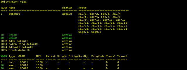
Step 6: Verify VLAs:
- Type command “show vlan” and enter
Step 7: Configuration SW Uplink Port as a Trunk:
|
Commands |
Details |
|
Switch# configuration terminal |
|
|
Switch
(config)# interface fa0/1 |
|
|
Switch (config)# description
Connection-to-Router |
|
|
Switch(config-if)#switchport
mode trunk |
Set
interface working with trunk mode |
|
Switch(config-if)#switchport
trunk allowed vlan 10,20 |
Set Vlans 10,20 into interface
as a Trunk |
|
|
|
- Type command “show interfaces trunk” and enter
Step 8: Configuration SW Down Link as an Access for end device
|
Commands |
Details |
|
Switch (config)# interface fa 0/2 |
Configuration interface ethernet |
|
Switch (config-if)# description
Connection-to-VLAN10 |
Add a description on interface |
|
Switch (config-if)# switchport mode access |
Set interface working with access mode |
|
Switch (config-if)# switchport
access vlan 10 |
Set Vlan 10 into interface |
|
Switch (config-if)# exit |
Exit config interface mode |
|
Switch (config)# interface fa
0/3 |
Configuration interface ethernet |
|
Switch (config-if)# description Connection-to-VLAN20 |
Add a description on interface |
|
Switch (config-if)# switchport
mode access |
Set interface working with access mode |
|
Switch (config-if)# switchport access vlan 20 |
Set Vlan 20 into interface |
|
Switch (config-if)# exit |
Exit config interface mode |
|
Switch(config)#do write |
Save
running-config to startup-config |


.png)


No comments:
Write Comments