Sunday, June 2, 2024

CCNA Lab Implement Inter-VLAN Routing

Network Topology: 

"Router on a stick" is a network configuration where a single router is connected to a switch via one physical interface but can manage multiple VLANs (Virtual Local Area Networks). In this scenario we used VLAN10 and VLAN20 for different groups for different purpose. 

This setup allows the router to route traffic between VLANs on the switch, acting as a gateway for inter-VLAN communication.


Objectives

  • Build the network and configuration basic Cisco Router
  • Configuration Gateway for all vlan at Router
  • Creating VLANs 
  • Configuration Trunking / Access at Switch Layer 2 

Step 1: In first setup, Cisco Router question to you about initial configuration dialog. You should be type “no” bypass this step


Step 2: You must be basic configuration for Router as following 

                      Commands

                             Details 

 Router>        

User mode

 Router> enable                                                   

Moving to Privilege mode

 Router# configuration terminal              

Moving to global config

 Router(config)# hostname R1 

Config hostname from Router to R1

 R1 (config)# banner motd #This is Router #

Config banner message 

 R1 (config)# enable password   cisco123enable 

Set password login from user mode to Privilege mode

 R1 (config)# service password-encryption

Request Router use service password encryption

 R1 (config)# line con 0

Configuration line console

 R1 (config-line)# password ccna

Set password login from console

 R1 (config-line)# login

Apply password into line console

 R1 (config-line)# exit

Exit configuration line console

 R1 (config)# line vty 0 4

Configuration line vty

 R1 (config-line)# transport in all

Set method access into router via line vty

 R1 (config-line)# password telnet

Set password login from live vty

 R1 (config-line)# login

Apply password on line vty

 R1 (config-line)# exit 

Exit configuration line vty


Step 3: IP Configuration for R1                                              

                       Commands 

                              Details 

 R1 (config)#

Privilege mode

 R1 (config)# interface gi0/0/1

Configuration interface eth (eth-mode)

 R1 (config-if)# description Connectio-to-SW1

Add a description on interface

 R1 (config-if)# no shutdown

Active interface

 R1 (config-if)# exit

Exit interface 

 R1 (config)# interface gi0/0/1.10 

Configuration sub interface

 R1 (config-if)# description Connection-to-VLAN-10

Add a description on sub interface

 R1 (config-if)# encapsulation dot1Q 10

Set Sub-interface working with VLAN10

 R1 (config-if)# ip address 10.10.10.1 255.255.255.0

Set ip address for sub interface

 R1 (config-if)# no shutdown

Active interface 

 R1 (config-if)# exit

Exit sun interface 

 R1 (config)# interface gi0/0/1.20 

Configuration sub interface

 R1 (config-if)# description Connection-to-VLAN-20

Add a description on sub interface

 R1 (config-if)# encapsulation dot1Q 20

Set Sub-interface working with VLAN20

 R1 (config-if)# ip address 10.10.20.1 255.255.255.0

Set ip address for sub interface

 R1 (config-if)# no shutdown

Active sub interface

 R1 (config-if)# exit

Exit configuration

 R1 (config)# write

Save running-config to startup-config


tep 4: Verify configuration on R1

  • Type command “show ip int brief” and enter

  • Type command “show running-config” and enter

  • Type command “show running-config | include interface GigabitEthernet0/0/1” and enter


Step 5: Configuration for Switch:

Commands

Details

Switch> enable

moving to Privilege mode

Switch#

Privilege mode

Switch# configuration terminal

moving to global config

Switch(config)#no ip domain-lookup

tells the SW not to search any wrong words typed in the CLI.

Switch(config)#vlan 10

add vlan 10

Switch(config-vlan)#name Grp10

Set description

Switch (vlan)# exit

exit vlan mode

Switch(config)#vlan 20

add vlan 10

Switch(config-vlan)#name Grp20

Set description

Switch (vlan)# exit

exit vlan mode


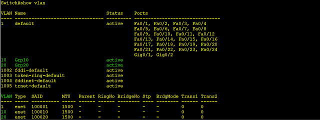
Step 6: Verify VLAs: 

  • Type command “show vlan” and enter


Step 7: Configuration SW Uplink Port as a Trunk:

                       Commands 

                              Details 

Switch# configuration terminal

Moving to global config

Switch (config)# interface fa0/1

Configuration interface ethernet

Switch (config)# description Connection-to-Router

Add a description on interface

Switch(config-if)#switchport mode trunk

Set interface working with trunk mode

Switch(config-if)#switchport trunk allowed vlan 10,20

Set Vlans 10,20 into interface as a Trunk


  • Type command “show interfaces trunk” and enter


Step 8: Configuration SW Down Link as an Access for end device 

Commands

Details

Switch (config)# interface fa 0/2

Configuration interface ethernet

Switch (config-if)# description Connection-to-VLAN10

Add a description on interface

Switch (config-if)# switchport mode access

Set interface working with access mode

Switch (config-if)# switchport access vlan 10

Set Vlan 10 into interface

Switch (config-if)# exit

Exit config interface mode

Switch (config)# interface fa 0/3

Configuration interface ethernet

Switch (config-if)# description Connection-to-VLAN20

Add a description on interface

Switch (config-if)# switchport mode access

Set interface working with access mode

Switch (config-if)# switchport access vlan 20

Set Vlan 20 into interface

Switch (config-if)# exit

Exit config interface mode

Switch(config)#do write

Save running-config to startup-config


Step 9: Verify VLAN Port Access  

  • Type command “show vlan” and enter


Thursday, May 30, 2024

Unlocking the Secrets of PoE Switches — A Complete Guide

Introduction to PoE Switches

Power over Ethernet (PoE) technology has revolutionized network design by combining data and power delivery into a single Ethernet cable. This advancement simplifies network setup and management, especially for devices like IP cameras, wireless access points, and VoIP phones.


Understanding PoE Standards

PoE (IEEE 802.3af)
Power Delivery: Up to 15.4 watts per port
Voltage Range: 44-57 V
Devices Supported: IP phones, basic IP cameras, and other low-power devices

PoE+ (IEEE 802.3at)
Power Delivery: Up to 25.5 watts per port
Voltage Range: 50-57 V
Devices Supported: Advanced IP cameras, wireless access points, and other medium-power devices

PoE++ (IEEE 802.3bt)
Type 3: Up to 60 watts per port
Type 4: Up to 100 watts per port
Voltage Range: 50-57 V
Devices Supported: High-power devices like PTZ cameras, high-performance wireless access points, and network lighting

Key Advantages of PoE Switches

Simplified Wiring
PoE reduces the need for multiple cables by delivering power and data through a single Ethernet cable, streamlining installation and reducing clutter.

Flexibility in Device Placement
Devices can be placed in optimal locations without the need to be near power outlets, enhancing network design flexibility.

Cost Efficiency
By eliminating the need for additional electrical infrastructure, PoE reduces installation and maintenance costs.

Scalability
PoE switches make it easier to add new devices to the network, supporting growth and changes without major reconfigurations.

Typical Use Cases for PoE Switches

IP Cameras

PoE is ideal for security and surveillance systems, allowing cameras to be placed in strategic locations without worrying about power sources.

Wireless Access Points (WAPs)

PoE enables optimal placement of WAPs to ensure maximum coverage and performance, crucial for enterprise and large-scale wireless networks.

VoIP Phones

PoE provides reliable power and data connectivity to VoIP phones, ensuring seamless communication in office environments.

Internet of Things (IoT) Devices

PoE supports a variety of IoT devices in smart buildings, from sensors to automation systems, facilitating efficient power and data management.


Choosing the Right PoE Switch

Power Budget

The total power capacity of the switch should meet or exceed the combined power requirements of all connected devices.

Number of Ports

Ensure the switch has enough ports to accommodate current devices and potential future expansions.

Managed vs. Unmanaged
 
Managed Switches: Offer advanced features like VLANs, Quality of Service (QoS), and network monitoring, providing greater control and security.
 
Unmanaged Switches: Simpler and cheaper, ideal for small networks or less complex installations.

Network Speed

Ensure the switch supports the necessary network speeds (e.g., Gigabit Ethernet) to meet performance requirements.

Installing and Configuring a PoE Switch

Installation Steps

Mounting the Switch: Install the switch in a suitable location, ensuring proper ventilation and accessibility.

Connecting Devices: Use Ethernet cables to connect PoE-enabled devices to the switch ports.

Powering the Switch: Connect the switch to a power source and turn it on.

Configuring the Network: For managed switches, access the switch’s configuration interface to set up VLANs, QoS, and other features.

Configuration Tips

VLAN Configuration: Segment the network to improve security and performance.

QoS Settings: Prioritize traffic to ensure critical applications receive adequate bandwidth.

Monitoring and Maintenance: Regularly monitor the switch’s performance and update firmware as needed.

Troubleshooting Common PoE Issues

Insufficient Power

Ensure the switch’s power budget can support all connected devices. If necessary, upgrade to a switch with a higher power capacity.

Connection Problems

Check cable quality and connections. Use certified Ethernet cables to avoid issues.

Device Compatibility

Verify that connected devices are PoE-compatible and meet the required standards.


Limitations of PoE Switches

Nonetheless, there are some limitations to PoE variation that you should be aware of:

Restrictions on distance: Typically, PoE switches can transmit over Ethernet up to a distance of up to 100 meters. The 100-meter distance restriction presents a challenge for large campuses, restaurants, and businesses implementing PoE. However, there are still devices like power extenders and powered fiber cables that can be used to extend the PoE range.


Power: If you require high power over poe networks, you must ensure that the power capacity of your PoE switches meets your requirements due to the power limitation imposed by PoE standards and Wattage.


Conclusion

PoE switches provide a versatile and efficient solution for modern network needs, combining power and data delivery into a single infrastructure. By understanding the standards, benefits, and proper selection criteria, you can optimize your network setup and enjoy the advantages of PoE technology. PoE switches are critical for building robust and scalable networks, whether for IP cameras, WAPs, VoIP phones, or IoT devices.


Wednesday, May 29, 2024

Enhancing Network Defense: A Deep Dive into Layer 2 and Endpoint Security

Layer 2 and Endpoint Security

In today's interconnected world, ensuring the security of both network infrastructure and endpoint devices is paramount. As cyber threats become more sophisticated, protecting your network at every layer is essential. This blog post explores the critical aspects of Layer 2 and endpoint security, highlighting best practices and strategies to safeguard your organization.


Understanding Layer 2 Security

Layer 2, also known as the Data Link Layer in the OSI model, is responsible for node-to-node data transfer and error detection in physical transmission. Security at this layer is crucial because it's where switches, bridges, and MAC addresses operate. Compromises at this level can lead to significant breaches, such as unauthorized network access and data interception.

Key Layer 2 Security Threats

MAC Address Spoofing: Attackers can change their device's MAC address to impersonate another device on the network.
 
VLAN Hopping: Exploiting vulnerabilities to gain unauthorized access to different VLANs.
 
ARP Spoofing: Manipulating the Address Resolution Protocol to redirect traffic to an attacker’s device.
 
STP Manipulation: Exploiting the Spanning Tree Protocol to create loops or network topology changes.

Best Practices for Layer 2 Security

Port Security: Configure switch ports to limit the number of MAC addresses that can be learned, reducing the risk of MAC address spoofing.
 
VLAN Segmentation: Isolate sensitive traffic by using VLANs and enforce strict VLAN tagging and trunk configurations.
 
Dynamic ARP Inspection (DAI): Enable DAI to validate ARP packets and prevent ARP spoofing.
 
BPDU Guard and Root Guard: Use these features to protect against malicious STP packets and maintain the integrity of your network topology.
 
Access Control Lists (ACLs): Apply ACLs at the switch level to control the traffic that is allowed to enter or leave the network segments.

Endpoint Security: The Frontline Defense

Endpoints, such as laptops, smartphones, and IoT devices, are often the entry points for cyberattacks. Securing these devices is essential for protecting sensitive data and maintaining network integrity.

Key Endpoint Security Threats

Malware and Ransomware: Malicious software that can encrypt files, steal data, or disrupt operations.
 
Phishing Attacks: Deceptive emails or messages designed to steal user credentials or deliver malware.

Unpatched Vulnerabilities: Exploited software vulnerabilities due to missing security updates.
 
Insider Threats: Malicious or negligent actions by employees that compromise security.

Best Practices for Endpoint Security

Antivirus and Anti-Malware: Deploy robust antivirus solutions to detect and remove malicious software.
 
Endpoint Detection and Response (EDR): Implement EDR solutions to monitor, detect, and respond to threats in real time.
 
Regular Patch Management: Ensure that all endpoint devices are regularly updated with the latest security patches.
 
Data Encryption: Encrypt sensitive data on endpoints to protect it from unauthorized access, especially if the device is lost or stolen.
 
User Education and Training: Conduct regular security awareness training to help users recognize and avoid phishing attempts and other threats.
 
Multi-Factor Authentication (MFA): Enforce MFA to add an extra layer of security beyond just usernames and passwords.

Integrating Layer 2 and Endpoint Security

For a holistic security strategy, it’s crucial to integrate Layer 2 and endpoint security measures. Here’s how you can achieve that: - 

Network Access Control (NAC): Use NAC solutions to enforce security policies at the point of network entry, ensuring that only compliant and authenticated devices can access the network.
 
Segmentation and Micro-Segmentation: Combine VLANs and endpoint security policies to segment the network and restrict access based on device type, user role, and compliance status.
 
Centralized Monitoring and Management: Utilize centralized security management platforms to oversee both network and endpoint security, providing unified visibility and control.
 
Incident Response Coordination: Develop coordinated incident response plans that address both network-level and endpoint-level threats, ensuring rapid and effective action.

Conclusion

Securing your network infrastructure at Layer 2 and protecting endpoint devices are both critical components of a comprehensive cybersecurity strategy. By implementing best practices and leveraging advanced security technologies, organizations can significantly reduce their risk exposure and enhance their overall security posture. Remember, a proactive approach to security, coupled with continuous monitoring and user education, is key to defending against the ever-evolving landscape of cyber threats.

The Linux command line for beginners

Overview

The Linux command line, also known as the terminal or shell, is a powerful tool that allows users to interact directly with the operating system. While it might seem intimidating at first, mastering a few basic commands can significantly enhance your efficiency and ability to manage your system. This overview introduces some essential commands that will help beginners navigate the Linux command line with confidence.


File and Directory Operations

Listing Files

  1. ls : Lists files and directories in the current directory. 
  2. ls -l : Lists files and directories with detailed information.
  3. ls -a : Lists all files, including hidden files.

Changing Directories

  1. cd [directory] : Changes the current directory to the specified directory.
  2. cd .. : Moves up one directory level.
  3. cd ~ : Changes to the home directory.

Creating Directories

  1. mkdir [directory] : Creates a new directory.

Removing Directories

  1. rmdir [directory] : Removes an empty directory.
  2. rm -r [directory] : Removes a directory and its contents recursively.

Copying Files and Directories

  1. cp [source] [destination] : Copies a file.
  2. cp -r [source_directory] [destination_directory] : Copies a directory and its contents.
  3. Moving/Renaming Files and Directories
  4. mv [source] [destination] : Moves or renames a file or directory.

Removing Files

  1. rm [file] : Removes a file.
  2. rm -r [directory] : Removes a directory and its contents.


Viewing and Editing Files

Viewing File Contents

  1. cat [file] : Displays the contents of a file.
  2. more [file] : Displays file contents one screen at a time.
  3. less [file] : Similar to more, but with backward navigation.
  4. head [file] : Displays the first 10 lines of a file.
  5. tail [file] : Displays the last 10 lines of a file.
  6. tail -f [file] : Displays the last 10 lines of a file and updates in real-time.

Editing Files

  1. nano [file] : Opens a file in the Nano text editor.
  2. vi [file] or vim [file] : Opens a file in the Vi/Vim text editor.

File Permissions

Changing File Permissions

chmod [permissions] [file] : Changes the permissions of a file or directory.
 
Example: chmod 755 [file] : Sets read, write, and execute permissions for the owner, and read and execute permissions for others.

Changing File Ownership

chown [owner]:[group] [file] : Changes the owner and group of a file or directory.
 
Example: chown user:group [file] : Changes the owner to 'user' and the group to 'group'.

System Information

Current Directory 

pwd : Prints the current working directory.

Disk Usage

  1. df : Displays disk space usage.
  2. du : Shows disk usage of files and directories.
  3. du -h [directory] : Shows disk usage in human-readable format.

System Information

uname -a : Displays all system information.
top : Displays running processes and system resource usage.
ps : Displays current processes.
ps aux : Shows detailed information about all running processes.

Networking

Checking Network Connectivity

ping [host] : Checks connectivity to a host.
ifconfig or ip a : Displays network interfaces and configurations.
netstat : Displays network connections, routing tables, and more.
ssh [user]@[host] : Connects to a remote host via SSH.

These commands are just the basics, but they cover many of the common tasks you'll need to perform in a Linux environment.

Basic Network Connectivity and Communications

Overview 

Basic network connectivity and communications refer to the fundamental concepts, components, and protocols that enable devices to connect and communicate over a network. Here's an overview of the key elements involved: -


Network Components

Devices: These include computers, smartphones, servers, and networking equipment like routers and switches.
 
Network Interface Card (NIC): Hardware that connects a device to a network.
Router: Directs data packets between networks.
Switch: Connects devices within a single network, filtering and forwarding data to the correct device.
 
Modem: Converts digital data to analog signals and vice versa for transmission over phone lines or cable systems.
 
Access Points: Provide wireless connectivity to devices.

Types of Networks

LAN (Local Area Network): A network that covers a small geographic area, like a home or office.
 
WAN (Wide Area Network): A network that covers a broad area, often a city, country, or even globally.
 
MAN (Metropolitan Area Network): A network that spans a city or large campus.
PAN (Personal Area Network): A network for personal devices, typically within a range of a few meters.

Network Topologies

Bus Topology: All devices are connected to a single central cable.
 
Star Topology: All devices are connected to a central hub or switch.
 
Ring Topology: Devices are connected in a circular format, with each device connected to two others.
 
Mesh Topology: Devices are interconnected, with multiple paths for data to travel.
 
Hybrid Topology: A combination of two or more topologies.

IP Addressing

IPv4: Uses 32-bit addresses, allowing for about 4.3 billion unique addresses.
 
IPv6: Uses 128-bit addresses, allowing for a vastly larger number of unique addresses.
 
Subnetting: Divides a network into smaller sub-networks to improve management and efficiency.

Protocols

TCP/IP (Transmission Control Protocol/Internet Protocol): The fundamental suite of protocols for the Internet, including:
 
TCP (Transmission Control Protocol): Ensures reliable, ordered delivery of a data stream between applications.
 
IP (Internet Protocol): Handles addressing and routing of packets between devices.
 
UDP (User Datagram Protocol): Provides a simpler, connectionless communication model.
 
HTTP/HTTPS (Hypertext Transfer Protocol/Secure): Used for transmitting web pages.
 
FTP (File Transfer Protocol): Used for transferring files.
 
SMTP (Simple Mail Transfer Protocol): Used for sending emails.
 
DNS (Domain Name System): Translates domain names to IP addresses.

Communication Models

OSI Model (Open Systems Interconnection) is a seven-layer model that standardizes communication functions:
  • Physical Layer
  • Data Link Layer
  • Network Layer
  • Transport Layer
  • Session Layer
  • Presentation Layer
  • Application Layer
TCP/IP Model: This model is more practical four-layer model:
  • Network Interface Layer
  • Internet Layer
  • Transport Layer
  • Application Layer

Wireless Networking

Wi-Fi: A family of wireless networking technologies based on the IEEE 802.11 standards.
 
Bluetooth: A standard for short-range wireless communication between devices.
Cellular Networks: Use radio waves to enable mobile device connectivity over long distances.

Network Security

Firewalls: Devices or software that control incoming and outgoing network traffic based on security rules.
 
Encryption: The process of encoding data to prevent unauthorized access.
VPN (Virtual Private Network): Extends a private network across a public network, enabling secure remote access.
 
Authentication: Verifies the identity of users and devices before allowing network access.

Summary

Basic network connectivity and communications involve various hardware components, network types, topologies, addressing methods, protocols, communication models, wireless technologies, and security measures. Understanding these elements is essential for designing, managing, and troubleshooting networks.

Networking Interview Questions & Answers

 Top Networking Interview Questions and Answers for 2024

Preparing for an entry-level network engineer position typically involves understanding both fundamental networking concepts and specific technical skills. Here are some of the top questions you might encounter in an interview for an entry-level network engineer position:


Can you explain the OSI model and its layers?

Answer: The OSI (Open Systems Interconnection) model is a conceptual framework used to understand network interactions in seven layers: Physical, Data Link, Network, Transport, Session, Presentation, and Application. Each layer has specific functions and protocols that facilitate communication across a network.

What is the difference between TCP and UDP?

Answer: TCP (Transmission Control Protocol) is connection-oriented, ensuring reliable and ordered delivery of data. It includes error-checking and flow control. UDP (User Datagram Protocol) is connectionless, faster, and does not guarantee delivery, order, or error checking, making it suitable for real-time applications like video streaming.

How does a router differ from a switch?

Answer: A router connects different networks and routes data packets between them, using IP addresses to determine the best path. A switch connects devices within the same network and uses MAC addresses to forward data to the correct destination within the network.

What is subnetting, and why is it used?

Answer: Subnetting divides a larger network into smaller, more efficient sub-networks (subnets). It improves network performance and security by reducing broadcast domains and isolating segments of the network.

Describe the function of ARP (Address Resolution Protocol).

Answer: ARP translates IP addresses to MAC addresses, allowing devices to communicate within the same local network. When a device wants to send data to another device on the same network, it uses ARP to find the recipient's MAC address associated with its IP address.

What is NAT (Network Address Translation), and why is it important?

Answer: NAT translates private IP addresses to a public IP address for devices within a local network to access the internet. It conserves public IP addresses and adds a layer of security by masking internal IP addresses from external networks.

Explain the difference between a hub and a switch.

Answer: A hub is a basic networking device that broadcasts data to all connected devices, resulting in potential collisions and inefficiencies. A switch, on the other hand, intelligently forwards data only to the specific device it is intended for, based on MAC addresses, reducing collisions and improving network performance.

What is VLAN (Virtual Local Area Network), and how does it work?

Answer: VLANs create logically separate networks within a physical network, segmenting traffic for improved performance and security. Devices within a VLAN can communicate as if they were on the same physical network, even if they are not.

How do you troubleshoot a network connectivity issue?

Answer: Steps include checking physical connections, verifying IP configuration with tools like ipconfig or ifconfig, using ping to test connectivity to other devices, and examining the network topology and configurations on routers and switches for misconfigurations or faults.

What is the purpose of a DHCP server?

Answer: A DHCP (Dynamic Host Configuration Protocol) server automatically assigns IP addresses and other network configuration parameters (like subnet mask, default gateway, and DNS servers) to devices on a network, reducing the need for manual configuration.

What is the difference between IPv4 and IPv6?

Answer: IPv4 is the fourth version of the Internet Protocol, using 32-bit addresses, allowing for about 4.3 billion unique addresses. IPv6 is the sixth version, using 128-bit addresses, significantly increasing the number of possible addresses and including improvements like simplified header format and better security.

Explain the purpose of DNS (Domain Name System).

Answer: DNS translates human-readable domain names (like www.example.com) into IP addresses (like 192.168.1.1) that computers use to identify each other on the network.

What is a default gateway, and why is it important?

Answer: A default gateway is a router that connects a local network to external networks, typically the internet. It acts as an access point for devices within the network to communicate with devices outside the local network.

How does a firewall work?

Answer: A firewall monitors and controls incoming and outgoing network traffic based on predetermined security rules. It establishes a barrier between a trusted internal network and untrusted external networks (such as the internet).

What is the difference between symmetric and asymmetric encryption?

Answer: Symmetric encryption uses the same key for both encryption and decryption, making it faster but requiring secure key distribution. Asymmetric encryption uses a pair of keys (public and private) where one key encrypts data and the other decrypts it, improving security at the cost of speed.

What is a VPN (Virtual Private Network), and how does it work?

Answer: A VPN extends a private network across a public network, enabling secure data transmission. It encrypts data sent over the internet, making it appear as if it is coming from the VPN server rather than the user's device, providing privacy and security.

Explain the concept of QoS (Quality of Service).

Answer: QoS manages network resources by prioritizing certain types of traffic to ensure optimal performance for critical applications, such as VoIP, video conferencing, and streaming services, reducing latency, jitter, and packet loss.

What is the difference between static and dynamic routing?

Answer: Static routing involves manually configuring routes in the routing table, which does not change unless manually updated. Dynamic routing uses protocols (like OSPF, EIGRP, or BGP) to automatically adjust routes based on current network conditions and topology changes.

What are some common network security threats, and how can they be mitigated?

Answer: Common threats include malware, phishing, DDoS attacks, and man-in-the-middle attacks. Mitigation strategies include using firewalls, intrusion detection/prevention systems, regular software updates, strong passwords, encryption, and user education.

What is MPLS (Multiprotocol Label Switching), and why is it used?

Answer: MPLS is a technique that directs data from one node to the next based on short path labels rather than long network addresses. It improves speed and controls the flow of network traffic, supporting efficient and scalable networks.


VLANs (Virtual Local Area Networks)

 VLANs (Virtual Local Area Networks)  

VLANs (Virtual Local Area Networks) are a fundamental concept in networking that allow you to segment a physical network into multiple logical networks. Here's a breakdown of each term you mentioned:

  • Management VLAN: This is a VLAN used for managing network devices such as switches, routers, and access points. Keeping management traffic separate from other types of traffic adds a layer of security and ensures that management functions remain unaffected by regular data traffic.

  • Data VLAN: Data VLANs are used to carry regular user data traffic. These VLANs separate user traffic logically, allowing for better network organization, management, and security.

  • Voice VLAN: Voice VLANs are used in Voice over Internet Protocol (VoIP) deployments to separate voice traffic from regular data traffic. This ensures better quality of service (QoS) for voice communications and helps prioritize voice packets over other types of data.

  • Default VLAN: The default VLAN is usually VLAN 1 on most switches. It's automatically assigned to all switch ports that haven't been explicitly assigned to another VLAN. While VLAN 1 can be used for regular data traffic, it's recommended to avoid using it for security reasons.

  • Native VLAN: The native VLAN is used in IEEE 802.1Q trunking protocol to carry untagged traffic. When frames arrive on a trunk port without a VLAN tag, they are placed into the native VLAN. It's essential to ensure that the native VLAN on both ends of a trunk link matches to avoid connectivity issues and potential security vulnerabilities.


VLANs are identified by a numeric value known as the VLAN ID (VID). The VLAN ID can range from 1 to 4094, allowing for up to 4094 different VLANs in a network. However, there are some reserved VLAN IDs:

VLAN 1: Default VLAN on most switches, often used for management purposes.

VLANs 1002 to 1005: Reserved for Token Ring and FDDI VLANs.

VLAN 4095: Reserved and cannot be used.

So practically, the usable VLAN range is typically VLAN 2 to VLAN 4094, providing a range of 4093 VLANs for segmentation and organization within a network.


Virtual Switch Instance

As for "VSI," it typically stands for "Virtual Switch Instance." In networking, a VSI is a virtualized instance of a switch. It's commonly used in provider edge (PE) devices in MPLS (Multiprotocol Label Switching) networks to provide connectivity and services to customer edge (CE) devices. VSIs allow service providers to offer Layer 2 VPN (Virtual Private Network) services to their customers, enabling them to extend their local area networks over a service provider's MPLS network.


Inter-VLAN 

Inter-VLAN routing is a networking technique used to facilitate communication between devices in different virtual local area networks (VLANs) within a larger network infrastructure. In traditional Ethernet networks, devices within the same VLAN can communicate directly with each other, but communication between devices in different VLANs requires a router.

How inter-VLAN routing typically works:

  • VLAN Segmentation: The network administrator configures VLANs on the network switches to logically segment the network into separate broadcast domains. Each VLAN represents a distinct group of devices that share common characteristics or requirements.

  • Router Configuration: A router or a layer 3 switch is configured to have an interface (or subinterface) in each VLAN that needs to communicate with other VLANs. These interfaces are often referred to as "router interfaces" or "SVIs" (Switched Virtual Interfaces).

  • Routing Configuration: Routing protocols (such as OSPF or EIGRP) or static routes are configured on the router to enable it to route traffic between the VLANs. This allows devices in different VLANs to communicate with each other.

  • Traffic Forwarding: When a device in one VLAN needs to communicate with a device in another VLAN, the traffic is sent to the router. The router examines the destination IP address of the traffic and forwards it to the appropriate VLAN based on its routing table.

  • Return Traffic: Similarly, return traffic from the destination device follows the same path through the router to reach the source device.

Inter-VLAN routing is crucial for allowing devices in different VLANs to communicate with each other while still maintaining the benefits of VLAN segmentation, such as improved security, reduced broadcast traffic, and better network performance. It enables efficient communication between different departments, services, or functions within an organization's network infrastructure.